How UPS and Diesel Generator Work Together: ATS Wiring & System Integration Guide
Meta Description: Learn how UPS systems and diesel generators integrate via ATS for uninterrupted power. Complete wiring guide, capacity matching tips, and automatic generator set best practices for critical power applications.
When power reliability is non-negotiable — data centers, hospitals, banks, or industrial facilities — a UPS (Uninterruptible Power Supply) combined with a diesel generator set and an Automatic Transfer Switch (ATS) forms the gold standard of backup power architecture. These two systems aren't redundant alternatives; they're complementary partners working in a carefully timed sequence to deliver zero-interruption power.
This guide breaks down how they collaborate, the correct ATS wiring topology, and the key parameters you need to configure correctly before commissioning.
Why UPS and Diesel Generators Are Better Together
A standalone UPS can bridge millisecond power gaps but typically only carries a battery runtime of 10–30 minutes on standard configuration. A diesel generator handles long-duration outages but takes 10–15 seconds to reach stable voltage and frequency after startup — during which sensitive IT loads would crash without protection.
The solution: chain them through an ATS.
|
Scenario |
UPS Role |
Diesel Generator Role |
|
Mains normal |
Conditions power, charges battery |
Standby |
|
Mains drops |
Instant battery switchover (0 ms) |
Starts, builds up voltage |
|
Mains out >15 sec |
Holds load during generator ramp-up |
Takes over as primary source |
|
Mains restored |
Switches back, recharges battery |
Runs unloaded 3–5 min, then stops |
This "UPS bridges, generator sustains" logic ensures the front-end load experiences zero interruption throughout the entire event.
How the Automatic Generator Set System Works: Step-by-Step Logic
1. Mains Normal — Standby Mode
l The ATS switch sits on the utility (mains) side
l UPS rectifier/charger runs normally; battery is kept at float charge
l The diesel automatic generator set waits in ready-to-start mode
2. Mains Fault — High-Speed Handoff Begins
When voltage drops below ~80% of nominal or frequency falls outside 45–55 Hz:
l At 0 ms: UPS detects the fault, cuts the rectifier path, and the inverter instantly draws from batteries. Critical loads see no interruption.
l At 0.5–2 sec: ATS confirms the fault isn't a transient spike (anti-nuisance delay), then closes a dry contact signal to the generator controller's START terminal.
l The automatic generator set cranks; the engine accelerates toward rated RPM (typically 1500 RPM / 50 Hz or 1800 RPM / 60 Hz).
3. Generator Ramp-Up — 10–15 Seconds
l The automatic voltage regulator (AVR) builds excitation; output climbs from 0 V toward rated 400 V (3-phase) or 230 V (single-phase)
l The generator controller monitors voltage ≥ 90% nominal and frequency within ±5% for 3–5 continuous seconds before issuing a "voltage qualified" signal
l During this window, the UPS continues running on battery — patiently holding the load
4. ATS Transfer — Generator Takes Over
Once the "voltage qualified" signal is received:
1. ATS opens the utility-side contacts
2. Mechanical linkage closes the generator-side contacts
3. Total transfer time: 50–200 ms (within UPS inverter tolerance)
4. Generator power flows through ATS into the UPS input terminal
5. UPS detects quality input, switches back to normal rectifier mode, and begins recharging batteries
The system now runs on generator-backed UPS power — stable indefinitely as long as fuel is available.
5. Mains Restoration — Graceful Return
l ATS monitors mains quality; waits 10–30 seconds of stable power before switching back (prevents false restores)
l ATS transfers load back to mains
l The automatic generator set does not stop immediately — it runs unloaded for 3–5 minutes to cool turbocharger and engine block
l After the cool-down cycle, the controller cuts fuel injection and the generator returns to standby
ATS Wiring: Correct Topology for UPS + Generator Integration
The standard wiring topology connects both mains and generator as inputs to the ATS, with the ATS output feeding the UPS input. See the logic below:
[Utility Mains] ──┐
├──► [ATS] ──► [UPS Input] ──► [UPS Output] ──► [Critical Loads]
[Generator Set] ──┘
↕
[Start Signal Wire]
(ATS → Generator Controller)
Key Wiring Steps
① Generator Output Terminals
Connect the generator's 3-phase output (R/S/T or L1/L2/L3), Neutral (N), and Ground (PE) to the ATS "backup source" input terminals. Use stranded copper cable — minimum 6 mm² cross-section (calculate based on actual load current). Ensure terminal crimping is torqued properly to prevent vibration-induced loosening.
② UPS Input Wiring (via ATS)
Route the ATS "normal source" output to the UPS mains input port. This ensures the UPS always receives power through the ATS, whether from mains or generator.
③ Battery Bank Connection
Connect the battery bank positive and negative through a DC circuit breaker to the UPS battery terminal. Polarity is critical — reverse connection damages the inverter circuitry immediately.
④ UPS Output to Critical Loads
Connect the UPS output to server racks, network switches, or other protected equipment. Consider installing a power distribution unit (PDU) for load monitoring.
⑤ ATS Start Signal Wire
A low-voltage dry contact wire runs from the ATS fault output terminal to the generator controller START input. This is the "intelligence wire" that makes your system a true automatic generator set — no manual intervention required.
⑥ Grounding System
Generator, UPS, ATS, and battery cabinet must all share a common earth electrode with individual ground conductors. Ground resistance must be ≤ 4 Ω per IEC/GB standards — this is a safety and EMI requirement, not optional.
Capacity Sizing: Why Generator Must Be Larger Than UPS
UPS systems use rectifier-front-end circuitry that draws non-linear (harmonic) current from the generator. This degrades the generator's output voltage waveform.
Rule of thumb: Diesel generator rated kVA = 1.5× to 2.5× the UPS kVA rating
For example, a 200 kVA UPS typically requires a 300–500 kVA automatic generator set.
Undersizing causes:
l Generator output voltage distortion (THD spikes)
l UPS falsely detecting "poor input quality" and staying on battery mode
l Potential generator AVR instability under harmonic load
Pro tip: Specify a PMG (Permanent Magnet Generator) excitation system for generator sets paired with UPS. PMG designs are inherently more resistant to harmonic distortion compared to standard shunt-excited AVRs.
Commissioning Checklist: 3-Stage Verification
Before going live, complete these three test stages:
Stage 1 — No-Load Test
l Power up the UPS without connecting any loads
l Verify mains-to-battery switchover works correctly
l Confirm battery charging current and voltage readings are nominal
Stage 2 — Transfer Test
l Simulate a mains outage (open the mains breaker)
l Confirm the automatic generator set starts without manual intervention
l Verify ATS completes transfer within 15 seconds
l Confirm the UPS carries the load seamlessly throughout — no load interruption
Stage 3 — Full Load Test
l Connect all critical loads
l Run the system continuously for at least 8–72 hours
l Monitor generator output: Total Harmonic Distortion (THD) < 5% is the target
l Check generator voltage and frequency stability under load transients
⚠️ Phase Sequence Verification (Mandatory): Before energizing, use a phase sequence meter to confirm the generator's output phase rotation (L1-L2-L3) matches the utility mains sequence. Reversed phase sequence will cause 3-phase motor loads (HVAC compressors, pumps) to spin backwards — with destructive results.
Common Mistakes to Avoid
|
Mistake |
Consequence |
Fix |
|
Undersized generator |
UPS stuck in battery mode |
Size to 1.5–2.5× UPS kVA |
|
No ATS start signal wire |
Generator won't auto-start |
Wire dry contact properly |
|
Incorrect phase sequence |
Motor load damage |
Verify before commissioning |
|
Poor grounding |
Equipment damage, EMI noise |
Single common earth ≤4 Ω |
|
Generator stops immediately after mains restore |
Thermal damage to turbo |
Always program 3–5 min cool-down |
|
Skipping load bank test |
Unknown failure point |
Always do Stage 3 full load test |
Summary
A properly integrated UPS + ATS + diesel automatic generator set system delivers what no single component can achieve alone:
l Millisecond response from the UPS battery inverter
l Unlimited runtime from the generator fuel supply
l Fully automatic operation via ATS control logic
l Clean, stable output — the UPS filters the generator's power before it reaches sensitive loads
Whether you're protecting a data center, a telecom base station, or a critical industrial process, this three-component architecture is the industry-proven answer to power continuity. The wiring itself is straightforward — but phase sequence, grounding, and capacity matching are the details that determine whether your system is truly reliable under real fault conditions.
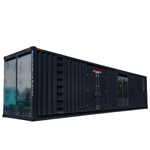
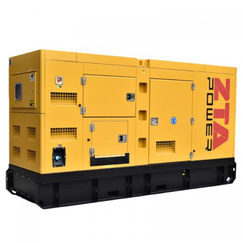
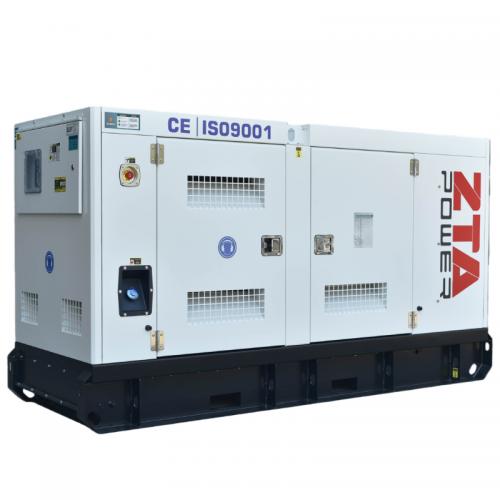
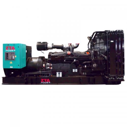
ZTA Power supplies industrial-grade diesel generator sets, silent generator sets, containerized generator sets, and ATS control panels for commercial and industrial power backup applications. Contact us for technical consultation and custom system sizing.
Tags: diesel generator, automatic generator set, UPS generator integration, ATS wiring, generator ATS, backup power system, uninterruptible power supply, generator set capacity, PMG generator, critical power

 Rede IPv6 suportada
 English
 français
 русский
 español
 português
 العربية
 Türkçe
 ไทย
ไทย Tiếng Việt
 Indonesia
  Filipino